86 Club Car DS Batteries

aaronmach1

New Member
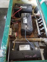
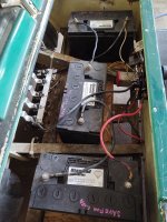
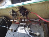
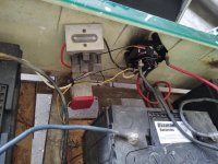
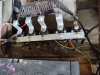
Just got 3 special made 12 volt golf cart batteries form the battery lady for my 1986 Club Car DS. Series together they are 37 volts. Then I connected them to the cart. One positive to the forward and reverse switch and the first batteries negative connected to a wire from the motor plus a wire from the charging port. Doesn't work. Nothing happens pushing the gas. Key on or off or in forward or reverse. Nothing happens at all. Any ideas please?
 

Attachments

  • IMG_20200624_171835856.jpg
    IMG_20200624_171835856.jpg
    114.9 KB · Views: 12
  • IMG_20200624_171847040.jpg
    IMG_20200624_171847040.jpg
    115.1 KB · Views: 13
  • IMG_20200624_171855158.jpg
    IMG_20200624_171855158.jpg
    83.9 KB · Views: 12
  • IMG_20200624_171904798.jpg
    IMG_20200624_171904798.jpg
    92.5 KB · Views: 11
  • IMG_20200624_171912471.jpg
    IMG_20200624_171912471.jpg
    98.7 KB · Views: 11

HotRodCarts

Cartaholic
The golf cart should be wired the same way as it was with six 6 volt batteries, minus 3 batteries. There's Club Car wiring diagrams in the resource section of the forum.
 

Rstaley

Cartaholic
From the pictures, it looks like you have a couple of wires reversed on the F/R switch. B+ from the battery pack should go to the left bottom connector of the switch. The top right should go to S1 on the motor. I know that you already have diagrams, but just for kicks, here is the one that I use for that model in a book that I wrote. I hope it helps and good luck, Ron.

club-car-resistor-wiring-diagram.jpg
 

aaronmach1

New Member
Im not sure if this is a diagram ive looked over yet. But i will try switching the 2 wires you suggested and see what happens. I have been wondering too, if i do hook something up wrong, could the batteries blow up or anything like that? Thanks a lot for the help Ron!
 

Rstaley

Cartaholic
They sure can. It's not real common, usually you will just turn your golf cart into a short term arc welder. A little trick I use when making connections on the high energy circuitry of the cart, is to "slap" the wire across the point where I intend to connect it. Just brush it quickly across the surface before committing it. If there is a spark, STOP and figure out what is wrong before going on.
 

Rstaley

Cartaholic
Does the solenoid energize (go clunk)? If it doesn’t, then you have issues on the low energy side that will have to be dealt with before you can go any farther. It would take a bunch of space here to walk you through all of that, but I wrote a book that is available FREE on my website that has a whole chapter written about that model (and several others), so here is a link to that to it. I hope you have a little experience with a meter because it gets a little “techy”, but it should help you (or someone that you can recruit to help you through the process). The book can be reached from the drop down menu at the top of the site, but this link will take you right to the chapter I am talking about.
Chapter 8-Electric - Welcome to Golf Cart Stuff Hodgepodge
 

aaronmach1

New Member
No clicks or clunks from the main solinoid. Micro switch on fr switch clicks when engaged, and when I push the throttle pedal down I can hear each of the micro switches click.
 

aaronmach1

New Member
Tested the main solinoid. 0 ohms between big pins. And with key on in forward and accelerator pedal pressed the small pins read zero volts.
 

aaronmach1

New Member
Very nice write you did. I tried the 22 gauge wire jumper and accidentally hit the big terminal on main solinoid and it blinded me (bright flash!) And the motor turned quick it sounded like. Redid it correctly and there's no activating the main solinoid.
 

aaronmach1

New Member
Another issue I just tried to hook up the charger the first time and it blew the barn breaker switch. Charger works fine so I assume it's somthing on the cart...
 

aaronmach1

New Member
The solonoids all have full power even when the key is off. So I unplugged the yellow wire that runs from main solinoid and should only have power when key on and fr switch in f. When I unplugged it the solonoids still have power. Somthing must be back feeding them 37 volts from the motor?
 

aaronmach1

New Member
Ok the constant key on or off 37 volt power supply to all the solonoids is the yellow wire coming from the silver box of micro switches. I have it wired to the bottom of the fr switch which is constant 37 volt power. Is that yellow wire in the wrong spot?
 

aaronmach1

New Member
Sorry for all the posts. Just fingered all the microswitches and the first one that should activate is just flopping. No spring back or click. I believe that I will try to find new switches.
 

Rstaley

Cartaholic
You’ve described several potential issues that need to be looked into. I think that if I were doing it, I’d disconnect the batteries altogether (to keep from damaging something) and just go with an ohmmeter and compare every wire on the cart with that of the schematic. For sure, you need to replace the switch that is “flopping”. The fact that the charger popped a breaker has got to be looked into. That could be dangerous. In all the time that I was working on these models, I did come across one where someone had reversed the logic to the switches, so that the B+ was common to all of the solenoids and the switches provided the B- (it will work either way), but I doubt you have that situation. I think that if you make sure it is just like the schematic it should work.
 

aaronmach1

New Member
I have replaced the bad microswitch. Now the solenoids all have zero volts until key is on and it's in either forward or reverse. Still no go when I push the accelerator. The diagram looks like all my wiring except I don't have the reverse buzzer. Any ideas I'm missing?
 

aaronmach1

New Member
Should all solonoids have power after the first click of pushing the accelerator? Or should they be zero volts untill the accelerator is pressed far enough to click their microswitch? Because once I trip the first microswitch then all solonoids get power.
 

aaronmach1

New Member
Just noticed somthing maybe major. On my fr switch the two bottom contacts have a jumper joining them both and they are supplied with full 36 volts always from b plus.see my pics above.
On your diagram the fr switch doesn't have the jumper. And the bottom left is 36 volts full time and the bottom right is 18v. I don't see how that makes sense but how would I get 18 v and is this my problem?
 
Top